Fixed boundaries
Learning targets
- Specify boundary identifiers
In many typical simulation setups
fixed physical boundary conditions on one or several boundaries
of the computational domain have to be specified.
This can be done by attributing an integer number as
boundary identifier in the layout and by attributing
physical properties to the corresponding boundary in the
file boundary_conditions.jcm (see also description
in the JCMsuite Parameter Reference).
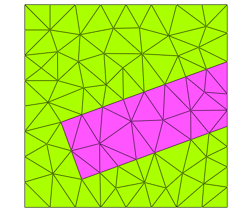
This geometry example specifies a square-shaped computational domain
with boundary identifier 1 at the left and right side of the
computational domain and boundary identifier 2 at the upper and lower
side of the computational domain. Note that boundary identifiers
specified for the computational domain (characterized through
the priority flag, Priority = -1) are attributed also at the
parts of boundary segments where other objects are overlapping
(here: where the tilted rectangle intersects with the computational
domain boundary).
The resulting geometry and mesh correspond to the following figure:

.jcm Input File
layout.jcm [ASCII]
 1
 2
 3
 4
 5
 6
 7
 8
 9
10
11
12
13
14
15
16
17
18
19
20
21
22
23
24
25
26
27
28
29
30
31
Layout2D {
  Name = "TutorialExample2D"
  UnitOfLength = 1e-09
  MeshOptions {
    MaximumSideLength = 40
  }
  Objects {
    Polygon {
      Name = "ComputationalDomain/Background"
      DomainId = 1
      Priority = -1
      Points = [-100 -100, 100 -100, 100 100, -100 100]
      Boundary {
        Number = [1 3]
        BoundaryId = 1
      }
      Boundary {
        Number = [2 4]
        BoundaryId = 2
      }
    }
    Parallelogram {
      Name = "Object"
      DomainId = 2
      Height = 200
      Width = 60
      RotationAngle = 20
      GlobalPosition = [40 -10]
    }
  }
}