3D Concepts
Learning targets
- Extruded 2D shapes create 3D geometries
- Stacking extruded layouts
- Defining textures on horizontal interfaces
- Using 3D geometrical primitives
- Updating existing layout.jcm files to new syntax
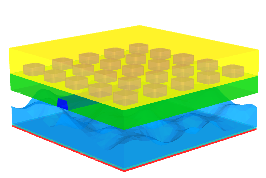
The following figure summarizes the ability of 3D mesh generation with JCMgeo:
Complicated geometries such as rough surfaces and waveguides reaching into the exterior domain can be easily created.
The construction of 3D geometries with JCMgeo is based on the extrusion of a 2D base layout in the  -plane into the
  -direction and the definition of geometrical primitives in 3D.
In different layers of the extrusion, different domain identifiers can be attributed to the extruded shapes. Furthermore, the geometry parameters such as the
 Radius for a circle can be reset across a layer interface. This allows to construct non-rectangular side-walls, e.g., corner roundings in z-direction, spherical shapes, etc.
Such an extruded layout reads as:
Layout3D {
  UnitOfLength = 1e-6
  Extrusion {
    Objects {
      # 2D definitions (x-y-coordinates)
      Polygon {
        DomainId = 1
      }

      Circle {
        Name = "Circle"
        DomainId = 2
        Radius = 1
      }

      ...
    }
    # extrusion to 3D (z-direction)
    MultiLayer {
      LayerInterface {
        BoundaryClass = Transparent
      }
      ...
      Layer {
        Thickness = 0.3
        DomainIdMapping = [1 1 2 1]
      }
      LayerInterface {
        GeometryValues = [
          Circle/Radius = 0.8
        ]
      }
      Layer {
        Thickness = 0.5
        DomainIdMapping = [1 1
                           2 2
                           3 11
                           4 12
                           5 13
                           ]
      }
      LayerInterface {
        BoundaryClass = Domain
      }
    }
 }
 Objects3D {
   # 3D definitions (x-y-z coordinates)
   Sphere {
     DomainId = 11
     Radius = 1
     GlobalPosition = [0 0 12]
   }
 }
}
Note
- The 3D layout contains an
Extrusionsection withObjectsin -coordinates (2D) and
a section for extrusion in the
  -direction (
MultiLayer). - The
MultiLayerstacks several layers upon each other in positive z-direction. - Each
Layerhas a specific thickness in -direction.
 - A
LayerInterfacesection between two layers or on top or bottom of all layers allows to reset geometry values of the 2D-base layout (Circle/Radius = 0.8) and to set boundary conditions. - Each layer contains a
DomainIdMapping. This defines domain identifiers attributed to the different 3D objects in this layer. Each 2D geometrical primitive of the 2D part of the layout carries an identifier,DomainId. Through theDomainIdMapping, the corresponding extruded 3D region in this layer of the 3DExtrusiongets attributed a new domain identifier. The domain identifier is used in the filematerials.jcmfor attributing material properties to the geometrical object.
Multiple extruded layouts are stacked on top of each other to construct a geometry as above with completely different geometries in different layers.
Please also see the following tutorial examples for a detailed description of specific layouts for 3D geometries, e.g., for layouts with non-rectangular sidewalls in z-direction..
JCMgeo allows for the addition of 3D primitives to a computational domain defined by an extrusion layout. These geometrical primitives like boxes, sphere, helices or cylinders behave very much like their 2D counterparts in that they share most attributes like DomainIds, Priorities or Ports. This means they can be used to cut parts of lower priority objects out, or fuse objects with the same DomainId together and align them relative to other objects or Ports of extruded objects in a particular layer. MeshOptions additionally include a MaximumVolume to control surface and volume meshes independently of each other. The 3D primitives are placed according to their GlobalPosition in 3D (or by relative alignment) and the rotation of the objects works by assigning a local coordinate system.
Layout3D {
  Extrusion {
    Objects {
      # 2D definitions (x-y-coordinates)
      Parallelogram { ... }
      ...
    }
    # extrusion to 3D (z-direction)
    MultiLayer{
      LayerInterface { ...}
      Layer { ... }
      ...
      LayerInterface { ... }
    }
  }
  Objects {
    Box { ... }
    Ellipsoid{ ... }
    Sphere { ... }
    SuperEllipsoid { ... }
    Helix { ... }
    Cone { ... }
    Cylinder { ... }
    ...
  }
}
A more detailed description of the different primitives and examples can be found here
Updating existing layout.jcm files to new syntax
here
Since JCMsuite Version 4, JCMgeo relies on a more capable syntax to define geometries. This requires a slightly adapted structure in the layout.jcm file. While the previous syntax is still recognized by JCMgeo, the current syntax allows for a simpler layout definition with more and improved features. Using the syntax highlighting, autocomplete and indentation features in JCMcontrol is the easiest way to create new and to update existing setups to the newest syntax. In the following, we highlight the major differences between JCMgeo Version 4 and the previous syntax:
Layoutsections are now referenced by the dimension of the grid the generate, i.e.Layout2DandLayout3Dfor 2D and 3D geometries.- All geometrical primitives are collected in an
Objectssection.- To convert a layout in 2D:
- Rename
LayouttoLayout2D- Create a section
Objectsenclosing all geometrical primitives- For an extruded layout in 3D :
- Rename
LayouttoLayout3D- Rename the
Extrusionsection enclosing theLayerandLayerInterfacestoMultiLayer- Create a new
Extrusionsection to open before the first 2D geometrical primitive and close after the freshly renamedMultiLayersection- In this new
Extrusionsection, create a sectionObjectsenclosing all 2D geometrical primitives
This requires a slightly adapted structure in the layout.jcm file.
