OpticalImaging
This post-process allows for the computation of the optical field image as it is formed by an electromagnetic field after passing an optical system. Phase front aberrations and the vectorial nature of light are taken into account. Furthermore, this post-process may deal with extended, partially coherent light sources which often serve as the illumination. The theoretical background and justification follow the presentations in [1], [2] and [3].
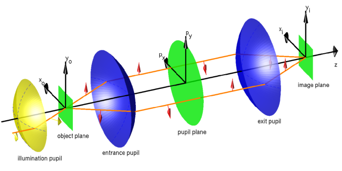
Figure “Idealized imaging system” shows a sketch of an idealized optical imaging system as covered by the post-process.

Idealized imaging system
It consists of the following building blocks aligned on the optical axis ( -direction):
- An illumination condenser which directs the light from different source points to the object.
- The object plane containing the scatterer.
- The entrance pupil collecting the light as transmitted and scattered through the object plane.
- The pupil plane containing the aperture. Further, phase aberrations and vectorial (polarization) effects are applied.
- The exit pupil focusing the light into the image plane.
- The image plane where the the actual image is formed.
The orange line indicates a light ray as it travels through the system. It is emitted as a single ray with certain polarization (yellow arrows) and hits the object in the object plane. There, it is scattered into different directions with different polarizations (red arrows). Each of the scattered rays travels independently through the optical system and is re-focused in the image plane.
This sketch is an abstraction as needed to explain how a structure is mapped from the object plane into the image plane. The entrance and exit pupils, and the pupil plane are purely virtual. In reality, the actual imaging system consists of a complicated arrangement of lenses and mirrors.
The input structure of the considered post-process has the following form:
PostProcess {
  OpticalImaging {
    InputFileName = ...
    OutputFileName = ...
    OpticalSystem {
      NumericalAperture = 0.6
      SpotMagnification = 100
      ...
    }
    InputGeometry {
      ...
    }
    OutputGeometry {
      ...
    }
  }
}
The “optical system” is the imaging system except the illumination. Its parameters are set in the section OpticalSystem. The sections InputGeometry and OutputGeometry allow to define user input and output planes different than the original object and image planes. Such a geometrical misalignment brings in further aberrations as discussed in the corresponding sections InputGeometry and OutputGeometry.
Use an export post-process to export the field distribution to a Cartesian grid in real space for visualization of the aerial image, for example:
PostProcess {
  ExportFields {
    FieldBagPath = "./project_results/fourier_coefficients_aerial_image.jcm"
    OutputFileName = "./project_results/aerial_image.jcm"
    OutputQuantity = ElectricFieldStrength
    Cartesian {
      GridPointsX = [-200e-6:5e-6:200e-6]
      GridPointsY = [-200e-6:5e-6:200e-6]
      GridPointsZ = 0
    }
  }
}
Bibliography
| [1] | Gross H. (editor), Handbook of Optical Systems, Volume II, III, Wiley-VCH 2005 |
| [2] | Kwok-Kit Wong A., Optical Imaging in Projection Lithography, SPIE 2005 |
| [3] | Peng. D, Hu P., Tolani V., Dam T., Tyminski J., Slonaker S., Toward a consistent and accurate approach to modeling projection optics, Optical Microlithography XXIII. Edited by Dusa, Mircea V.; Conley, Will. Proceedings of the SPIE, Volume 7640 |