Propagating Mode
In this tutorial project the eigenmodes in the coupling region of a directional coupler are computed. The setup essentially consists of a thin high-refractive index layer (waveguide layer) on a substrate, and of two parallel top ridges / fins yielding formation of localized waveguide modes. The super space is filled by air.
The layout is constructed from several parallelograms.
The first parallelogram is used as computation domain,
as defined by the Priority parameter.
6 7 8 9 10 11 12 13 14 15 16 | Objects {
Parallelogram {
Name = "ComputationalDomain"
Height = 5
Width = 16
DomainId = 1
Priority = ComputationalDomain
Port = South
Boundary {
BoundaryId = 1
}
|
Any further geometrical object in the layout.jcm file which intersects the computational domain is cut off.
The boundary of the computational domain is given a BoundaryId which refers to an entry in the boundary_conditions.jcm file:
1 2 3 4 | BoundaryCondition {
BoundaryId = 1
Electromagnetic = TangentialMagnetic
}
|
TangentialMagnetic sets the tangential component of the magnetic field to 0 on the boundary.
The involved materials of the coupler are defined in the materials.jcm file.
One of them is absorbing, hence the permittivity is a complex number:
8 9 10 11 12 13 | Material {
DomainId = 2
Name = "InP"
RelPermeability = 1.0
RelPermittivity = 10.0489+0.23i
}
|
The project file defines the Propagating Mode project to be solved:
1 2 3 4 5 6 7 8 9 10 11 12 13 14 15 16 17 18 19 20 21 22 23 24 | Project {
InfoLevel = 3
Electromagnetics {
TimeHarmonic {
PropagatingMode {
Lambda0 = 1.55e-06
Accuracy {
Precision = 0.01
FiniteElementDegree = 2
Refinement {
MaxNumberSteps = 5
PreRefinements = 0
}
}
SelectionCriterion {
NearGuess {
Guess = 3.2
NumberEigenvalues = 4
}
}
}
}
}
}
|
For the computation of propagating modes, the vacuum wavelength of the computed modes is defined by setting Lambda0.
The Precision parameter controls the accuracy of the simulation, i.e. of the computed eigenvalues.
A smaller value will lead to more accurate results.
The Refinement section is set to allow mesh refinements, in order to reach the defined accuracy.
The computation of eigenmodes is then performed on a hierarchy of refined meshes and the convergence of eigenvalues is monitored.
Once the eigenvalues are converged to Precision/100 the loop is stopped.
A MaxRefinementSteps value greater zero sets the refinement of the mesh to a self-adaptive mode.
An error estimator chooses mesh cells which still have a large error and only those are refined.
In comparison to uniform mesh refinement, this can significantly save computational effort.
In order to search for the eigenmodes a Guess is defined for the effective refractive index of the modes.
The FEM solver then searches for N= NumberEigenvalues eigenmodes closest to the guess value.
Starting the project will invoke the eigenmode computation and show the convergence during the mesh refinement loop:
           1. effective_refractive_index
  level                     eigenmode     delta  ratio
------------------------------------------------------
      0  3.194373e+00 + 0.024677e+00i       -/-    -/-
      1  3.194431e+00 + 0.024670e+00i  1.84e-05    -/-
      2  3.194418e+00 + 0.024675e+00i  4.30e-06   4.27

           2. effective_refractive_index
  level                     eigenmode     delta  ratio
------------------------------------------------------
      0  3.194332e+00 + 0.024650e+00i       -/-    -/-
      1  3.194391e+00 + 0.024641e+00i  1.85e-05    -/-
      2  3.194378e+00 + 0.024646e+00i  4.31e-06   4.29

           3. effective_refractive_index
  level                     eigenmode     delta  ratio
------------------------------------------------------
      0  3.188349e+00 + 0.027271e+00i       -/-    -/-
      1  3.188369e+00 + 0.027276e+00i  6.37e-06    -/-
      2  3.188356e+00 + 0.027276e+00i  3.90e-06   1.63

           4. effective_refractive_index
  level                     eigenmode     delta  ratio
------------------------------------------------------
      0  3.188314e+00 + 0.027250e+00i       -/-    -/-
      1  3.188332e+00 + 0.027254e+00i  5.96e-06    -/-
      2  3.188320e+00 + 0.027254e+00i  3.88e-06   1.54
When visualizing the refined mesh, one can observe that mainly mesh cells in the vicinity of the waveguides where the modes are localized have been refined by the algorithm:
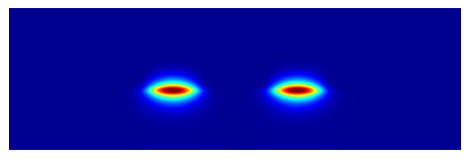
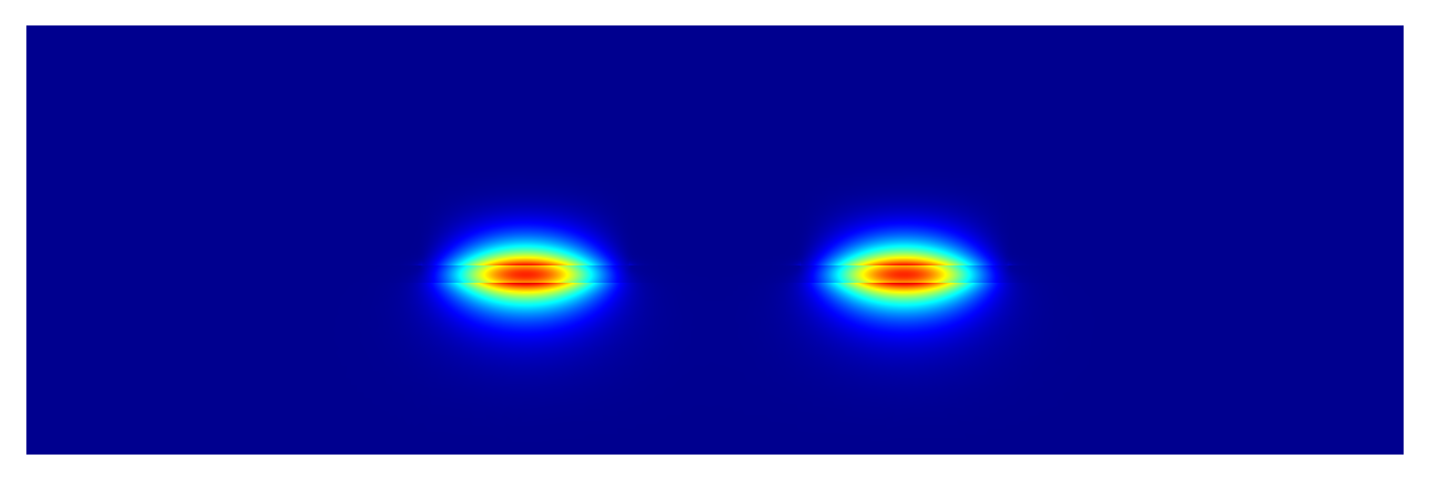
Field intensity plots of two computed modes:
Decreasing the parameter Precision to smaller numbers will lead to more refinement steps up to the maximum specified number MaxNumberSteps.
It is also possible to specify PreRefinements which will lead to a number of uniform mesh refinement steps preceding the computation.


