Light Scattering
This example demonstrates how to set up a simple electromagnetic scattering project: Scattering of a plane wave from a cylinder. The cylinder is assumed to have infinite length, therefore the computational domain can be restricted to a 2D cross section. The layout file describes the geometry: The cylinder cross section is defined by a circle, and the computational domain with background material is defined by a parallelogram:
1 2 3 4 5 6 7 8 9 10 11 12 13 14 15 16 17 18 19 20 21 22 | Layout2D {
UnitOfLength = 1e-6
MeshOptions {
MaximumSideLength = 0.5
}
Objects {
Parallelogram {
Height = 3
Width = 3
DomainId = 1
Priority = ComputationalDomain
Boundary {
Class = Transparent
}
}
Circle {
Radius = 1.0
RefineAll = 3
DomainId = 2
}
}
}
|
The UnitOfLength is set to 1e-6 which means that all geometrical quantities are given in microns ( ). Furthermore, an initial mesh refinement / fineness is defined by the parameter
 MaximumSidelength.
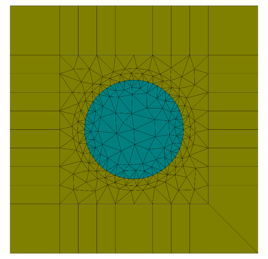
The following figure shows the triangulated geometry:
Performing scattering simulations, the structure of interest is usually embedded into an infinite exterior. Often the device or structure is mounted onto a substrate, and an ambient environment above the domain of interest is present. Substrate and superstrate are usually modelled as extending to infinity. In a non-periodic setting, the domain of interest extends also horizontally to infinity. Numerically this setup is realized by applying so-called transparent boundary conditions to the boundaries of the computational domain. JCMsuite uses a high-performance, self-adaptive perfectly matched layer (PML) implementation, which assures that the numerical results reproduce exactly the solution of the infinite domain. The triangulation shows the separation of the computational domain into an interior, partitioned by triangles, and the exterior, partitioned by quadrilaterals. These quadrilaterals model the infinite exterior.
Identifier (DomainId) attributed to Circle and Parallelogram allow to specify domain properties in the materials.jcm file.
In JCMview these are visualized by different colors .
In the materials.jcm file the permittivity and permeability are defined for all DomainIds appearing in the layout:
1 2 3 4 5 6 7 8 9 10 11 | Material {
DomainId = 1
RelPermeability = 1.0
RelPermittivity = 1.0
}
Material {
DomainId = 2
RelPermeability = 1.0
RelPermittivity = 2.25
}
|
To complete the physics of the project setup, incident plane waves are defined in the sources.jcm file.
Several SourceBags are treated as independent sources and are efficiently simulated yielding independent results.
1 2 3 4 5 6 7 8 9 10 11 12 13 14 15 16 17 18 19 20 | SourceBag {
Source {
ElectricFieldStrength {
PlaneWave {
K = [0, -4.05e+06, 0]
Amplitude = [0 0 1]
}
}
}
}
SourceBag {
Source {
ElectricFieldStrength {
PlaneWave {
K = [-4.05e+06, 0, 0]
Amplitude = [0 1 0]
}
}
}
}
|
The numerical complexity of the project depends on the physical setup as described above. On the other hand, also the required accuracy impacts the numerical effort. The numerical accuracy setting is specified in the project file:
1 2 3 4 5 6 7 8 9 10 11 12 13 | Project {
InfoLevel = 3
StorageFormat = Binary
Electromagnetics {
TimeHarmonic {
Scattering {
Accuracy {
Precision = 0.02
}
}
}
}
}
|
The accuracy of the computation is controlled by the parameter Precision. This parameter can be understood as a dimensionless slider to control accuracy of a simulation. Smaller values lead to more accurate solutions. How the specified Precision value relates to the output the user is finally interested in, depends on the application and the quantity of interest, and the specific setup.
Also the physical model to be solved is chosen in the project files.
Here, an electromagnetic time-harmonic scattering project is defined.
Since a time-harmonic model is used, the different sources in the source file are required to have the same frequency.
The StorageFormat parameter defines if and in which format the Finite Element solution is written to the hard drive.
Solving a project leads to creation of a result file directory with name <project_file>_results
where <project_file> is the name of the project file (without file suffix).
The Finite Element solution is saved to this result directory as fieldbag.jcm in Binary format.
Further, so-called PostProcesses can be defined in the project file.
These are executed after the solution process.
Here, the ElectricFieldEnergy in the various domains is obtained by numerical integration of the solution field.
The result is written to a file with specified OutputFileName:
1 2 3 4 5 6 7 | PostProcess {
DensityIntegration {
OutputFileName = "./project_results/electric_field_energy.jcm"
FieldBagPath = "./project_results/fieldbag.jcm"
OutputQuantity = ElectricFieldEnergy
}
}
|
