Coupling into Fiber
In this example we consider the coupling of a single photon emitter into an optical fiber. Details on the system and the numerical method can be found in [1].
The single photon source consists of a quantum dot (QD) embedded into a spherical micro-lens made from gallium arsenide (GaAs). An underlying Bragg multilayer structure reflects the light emitted by the QD back into the upper hemisphere. The light is coupled into an optical fiber above the QD consisting of a homogeneous fiber core and fiber cladding (see figure below).
The computation exploits the radial symmetry of the setup. Therefore, the shape of the lens can be created by a Boolean intersection between a circle sector and a parallelogram defined in the file layout.jcm:
    BooleanOperation {
      Operator = Intersection
      DomainId = 1
      Priority = 4

      A {
        CircleSector {
          Name="Lens"
          Radius = 3180.07936507937
          AngleRange = [53.3111315227145 90]
          RefineAll = 2
          Port = Point1
          GlobalPosition = [1900 0]
        }
      }
      B
      {
        Parallelogram {
          Port = Point2
          GlobalPosition=[1900 0]
          Width = 10000
          Height = 10000
        }
      }
    }
For the fiber mode computation, the geometry of the fiber cross section can be extracted from the layout of the full system in the file fiber_modes/layout.jcm:
ExtractFace {
  InputFileName="../layout.jcm"
  NormalDirection=Y
  Orientation=Outward
}
The determination of the coupling efficiency happens in three steps:
First, the propagation modes propagation modes of the fiber are determined.
Next, the field emitted by the QD has to be simulated. The extension of the QD is relatively small compare to the wavelength within the micro lens. It can be therefore modelled as a point-like dipole source dipole source.
In the last step, the overlap integral overlap integral between the propagating fiber modes and the emitted field is determined. The coupling efficiency is given by the overlap divided by the total power emitted by the dipole. The dipole emission and the overlap integral can be obtained by two post processes DipoleEmission and ModeOverlap defined in the file project.jcmp:
PostProcess {
  DipoleEmission {
    FieldBagPath = "project_results/fieldbag.jcm"
    OutputFileName = "project_results/dipole_emission.jcm"
    Format = JCM-ASCII
  }
}

PostProcess {
  ModeOverlap {
    FieldBagPath = "./project_results/fieldbag.jcm"
    ModeFileName = "./fiber_modes/project_results/fieldbag.jcm"
    OutputFileName = "./overlap.jcm"
  }
}
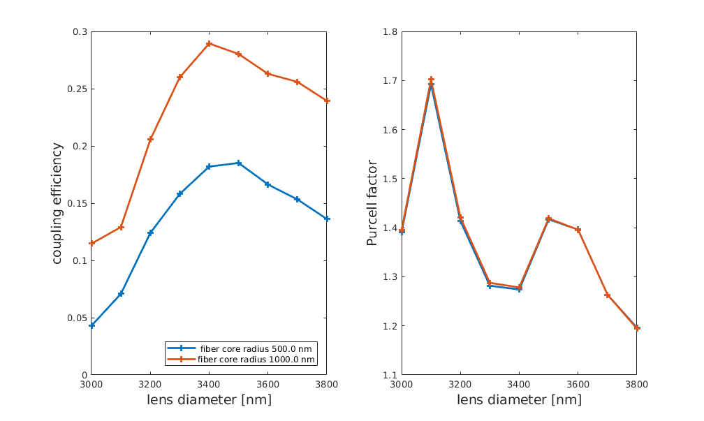
The following figure shows a scan of the coupling efficiency into the fundamental fiber modes and the Purcell factor [*] as a function of the lens diameter  and the fiber core diameter
  .
.
| [*] | The Purcell factor is the quotient between the dipole emission in the structure and the emission of a dipole in a homogeneous space with the background material at the dipole position. |
| [1] | P.-I. Schneider, et al., Numerical optimization of the extraction efficiency of a quantum-dot based single-photon emitter into a single-mode fiber. Optics Express 26, 8479 (2018). https://doi.org/10.1364/OE.26.008479 |

