VCSEL
A vertical-cavity surface-emitting laser (VCSEL) is a specific, miniaturized semiconductor laser diode. The cavity is typically formed by Bragg mirrors (distributed Bragg reflectors, DBR), and laser beam emission is perpendicular to the top surface. This tutorial example shows how to setup the complex VCSEL geometry and how to compute efficiently cavity modes with their characteristic 3D mode profile, the resonance wavelength and quality factor (Q-factor). The setup follows closely an example from the literature (Bienstmann et al, 2001). The geometry is rotationally symmetry, you can therefore use the resonance mode solver in a cylindrical coordinate system to compute the resonances.
The geometry
(a 2D geometry which is rotated around the y-axis to yield the 3D device geometry)
and various meshing parameters are defined in the file layout.jcm.
In this specific case the all layers (DBR, active layers, aperture layers, cavity layers) are
defined as polygons in absolute coordinates, with sub-nm precision.
Choose the meshing options such that a not too fine discretization of the relatively large
computational domain is obtained. (In this case the thinnest layer is only
 thin while the
diameter of the device is about
 .
Anisotropic meshing can reduce computational effort significantly in this case.
5 6 7 8 9 | CoordinateSystem=Cylindrical
MeshOptions {
TinyFeatureSize = 200
MinimumMeshAngle = 5
RemoveInnerConstraints = no
|
The TinyFeatureSize option essentially switches off meshing in all layers thinner than
TinyFeatureSize = 100 units of length.
The MinimumMeshAngle option allows for sharp triangles.
The RemoveInnerConstraints option allows for subgridding in vertical direction by placing
several thin layers of the same material close to each other (which is done in the central
cavity region in this case).
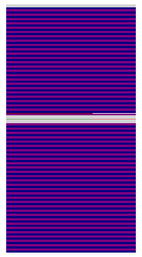
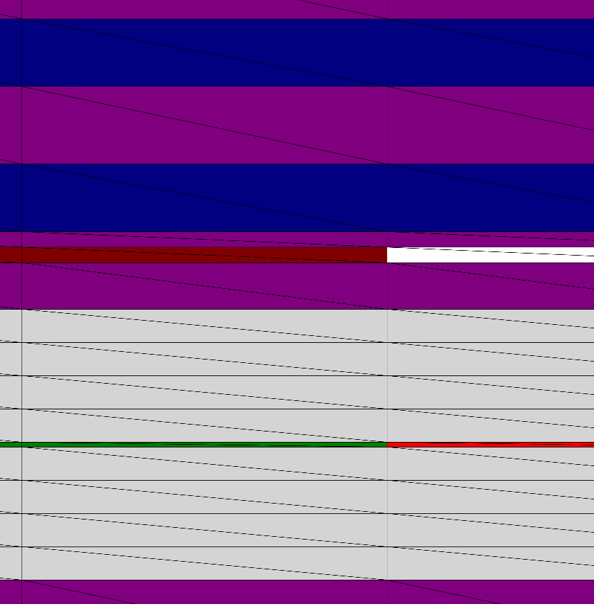
The following figure shows the geometry (left, note the top / bottom DBRs with 25 / 30 quarter wave layer pairs) and parts of the triangulation (right, detail, note the very thin active layer, and note the anisotropic mesh with very pointed triangles).
 |
 |
The material permittivities for the various layers are defined in the file materials.jcm.
The numerical project parameters are defined in the file project.jcmp:
1 2 3 4 5 6 7 8 9 10 11 12 13 14 15 16 17 18 19 20 21 22 23 24 25 26 27 28 29 30 31 32 33 34 35 36 37 | Project {
Electromagnetics {
TimeHarmonic {
ResonanceMode {
FieldComponents = Electric
BlochVector = [0, 0, 1]
Accuracy {
FiniteElementDegree = 4
Refinement {
MaxNumberSteps = 0
}
Precision = 0.001
}
SelectionCriterion {
          NearGuess {
            Guess = 1.921e+15
            NumberEigenvalues = 1
          }
}
        PML {
          Compartment {
            Direction = X
            StartThicknessLevel = 7
          }
          Compartment {
            Direction = Y
            StartThicknessLevel = 0
          }
          Compartment {
            Direction = -Y
            StartThicknessLevel = 7
          }
        }
}
}
}
}
|
Computation of fundamental modes in a rotationally symmetric coordinate system
is chosen by the options
FieldComponents = ElectricRYPhi and
BlochVector = [0, 0, 1].
(Compare definitions for computation in 3-dimensional, cylindrical geometries in the
Parameter Reference).
The numerical settings are set to a relatively high accuracy. The guess value for the mode solver is set to a value close to the resonance (a good starting value is helpful, as the structure supports a large number of modes, which are closely spaced. The guess value can be obtained by a well-educated guess, from the literature, or by using numerical scans at lower numerical resolution):
NearGuess {
Guess = 1.921e+15
NumberEigenvalues = 1
}
The setting for the transparent boundary conditions (PMLs) is chosen such that also the very low leakage to the radial direction is well resolved and does not lead to artificial reflections:
PML {
Compartment {
Direction = X
StartThicknessLevel = 7
}
Compartment {
Direction = Y
StartThicknessLevel = 0
}
Compartment {
Direction = -Y
StartThicknessLevel = 7
}
}
The file project.jcmp further includes post processes to export the computed field
distributions to 2D cross sections through the computed 3D solution.
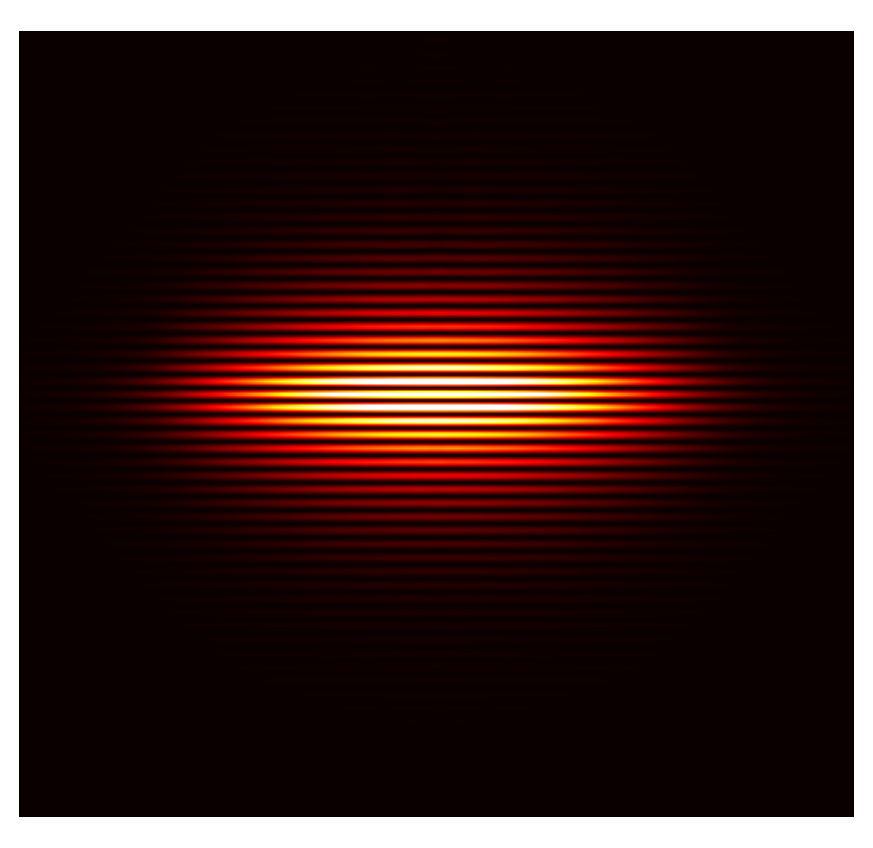
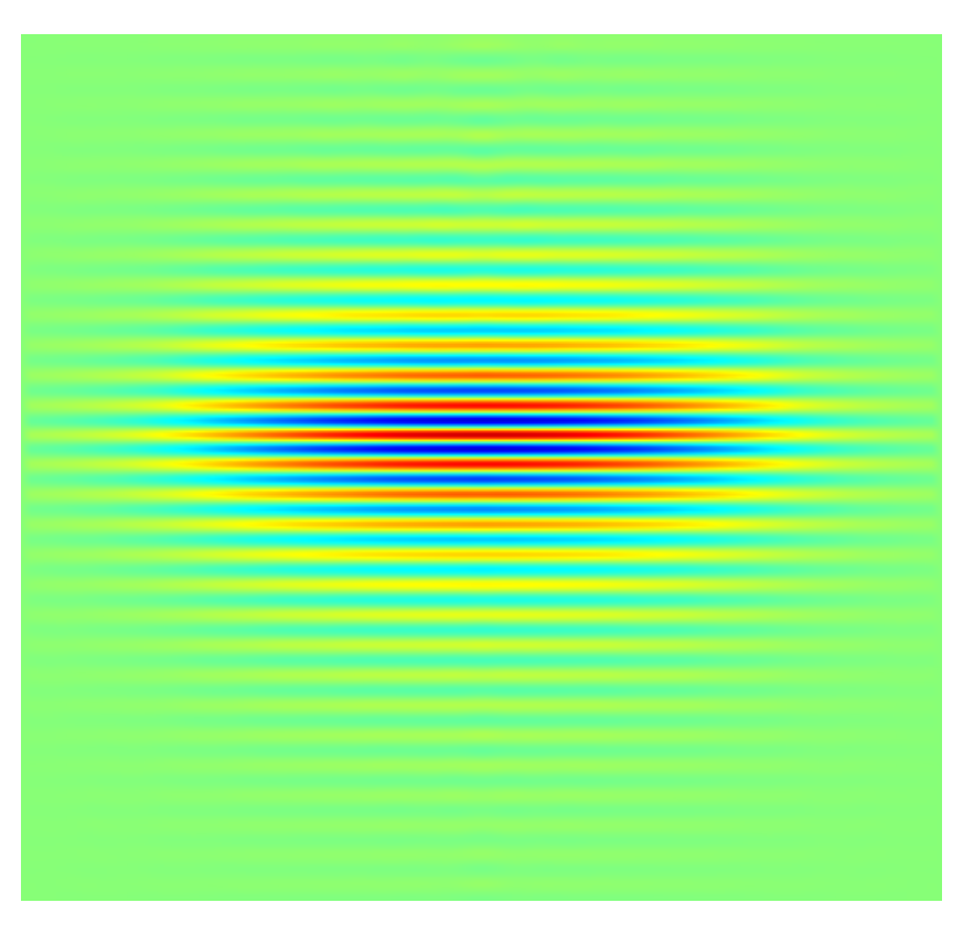
The following figure displays cross sections through a plane parallel to the symmetry axis,
and through the center of the cavity, visualizing the light intensity distribution (left)
and the real part of a field vector component ( ):
):
 |
 |
The project folder also includes a script run_project.m, which allows for
automatic setup of the geometry, which invokes the FEM solver,
and which computes resonance wavelength and Q-factor from the computed eigenvalue.