PlaneWave
| Type: | section |
|---|---|
| Appearance: | multiple |
Specifies a time-harmonic plane wave,

There are three ways for a user input of a plane wave:
- Specify all components of
 and
and  , see here.
 - Specify incidence angles
 and polarization in terms of
  -components, see here.
 - Specify pupil
 -coordinates and polarization in terms of
  -components or
  -components, see here.
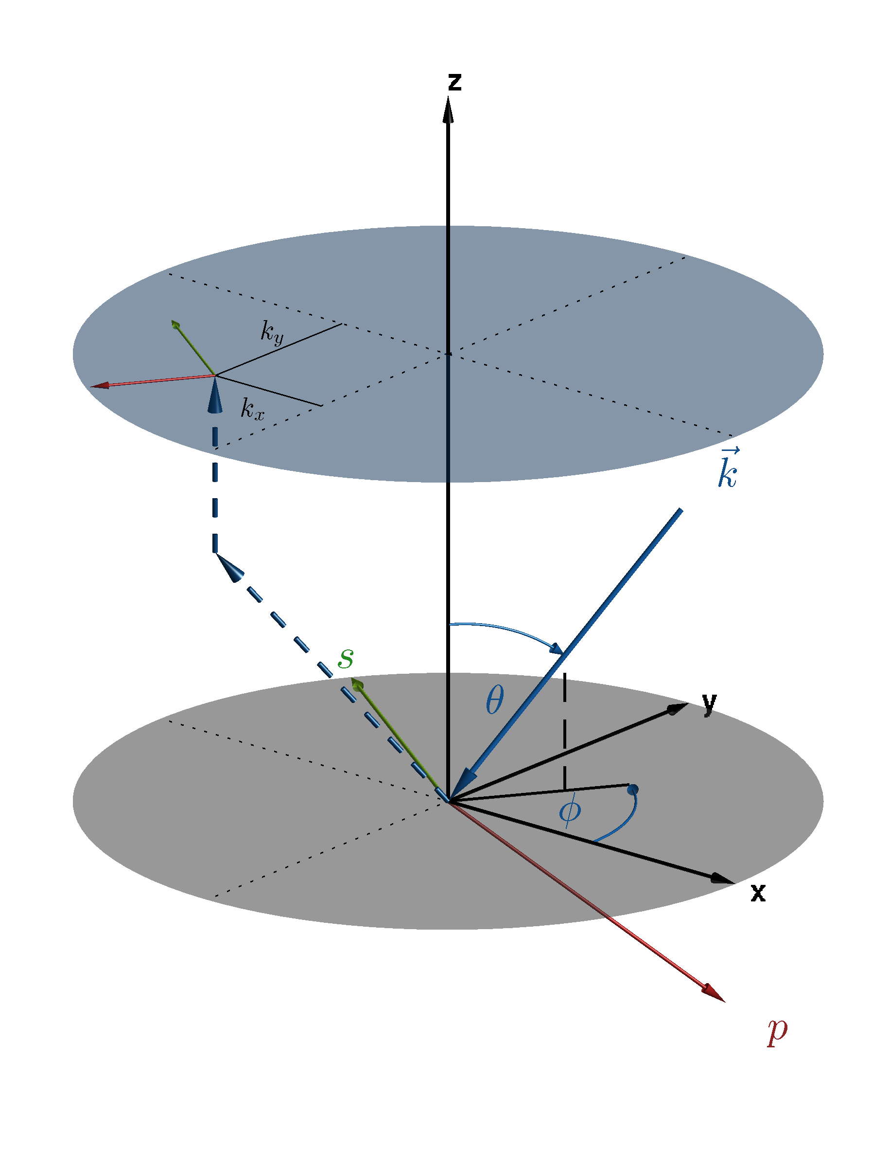
The following figure show the situation for a incident plane wave from below and from top.

Plane Wave from below. The upper light blue plane is the  -plane.

Plane wave from above. The upper light blue plane is the  -plane.
Definition by  and
and 
In order to be a solution of Maxwell’s equations in an homogeneous medium it is required that the wave vector  and the complex-valued field amplitude
  are perpendicular, e.g.,
  The wave vector,
  , is related to the vacuum wavelength,
  , of the plane wave and to the refractive index,
  , of the medium from where the plane wave is coming in by
  .
.
When globally defined, e.g, when DomainId and BoundaryId are left empty, this field is interpreted as an incident plane wave light source. Then, the wavevector  is specified in the medium from where the plane wave is coming in. When the exterior domain of the corresponding geometry is layered, then Maxwell’s equations are first automatically solved for the unstructured layered media stack under the given plane illumination, and the corresponding solution is applied as source field.
.. a field is specified which solves Maxwell’s equation within the layered media stack under the given illumination.
Amplitude (polarization and phase) and K (propagation direction and wavelength) deliver a unique description of plane waves. For convenience, JCMwave provides some more options to define a plane wave:
Definition by 
ThetaPhi defines the propagation direction. With the rotation matrices  and
and  and the unit vector
  the wave vector
  is calculated as follows:

With the Parameter Incidence one specifies if  points in direction of
  (
(FromBelow) or  (
(FromAbove). The refractive index  is the refractive index of the lower half space (Incidence=FromBelow) or the upper half space (Incidence=FromAbove). We further need to define vacuum wavelength Lambda0 or alternatively the angular frequency Omega, that is

with  being the speed of light in vacuum.
We use the 2-vector parameter SP,
 ![[\VField{\VField{H}}_s, \VField{\VField{H}}_p]](_images/math/5a0780398bab7cffcd9ce60c22eaaff793528396.png) to specify the polarization of the plane wave:
to specify the polarization of the plane wave:

with

Definition by  -coordinates
Another option to provide the propagation direction is Sigma,

The  component of of the incident plane wave is computed from the relation
  .
.
Ray optically the  plane shown in the above figures can be regarded as the pupil plane of an optical system with optical axis in
  -direction imaging the incident plane wave towards infinity. The so mapped incident plane wave is perpendicular to the
  -plane and the field vector lies within the
  -plane.
Instead of specifying the  -components of the polarization one alternatively can define the polarization in the Cartesian coordinates of the
  pupil plane:

with
