Periodic boundaries III
Learning targets
- Periodic boundary conditions
- 2D-periodic hexagonal lattice of 3D objects with transparent boundary conditions in the third dimension
- Usage of a rectilinear unit cell
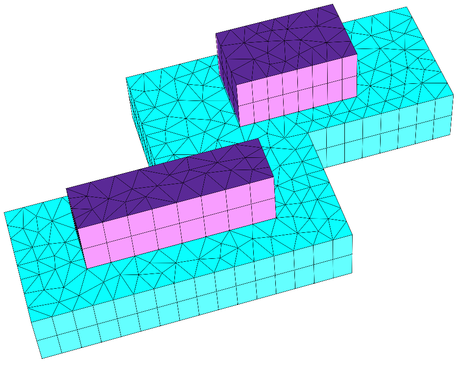
This example constructs the unit cell for a periodic array of nano-scale lines on top of a substrate. The periodic lattice is hexagonal, but we use a rectilinear unit cell to avoid unfavorable intersections of the unit cell boundary with the actual structure
The following figure shows an image of parts of the geometry and mesh:
The periodic boundary conditions are defined in the 2D section of the 3D layout, the transparent boundary conditions are applied in the Extrusion section of the layout.
.jcm Input File
layout.jcm [ASCII]
 1
 2
 3
 4
 5
 6
 7
 8
 9
10
11
12
13
14
15
16
17
18
19
20
21
22
23
24
25
26
27
28
29
30
31
32
33
34
35
36
37
38
39
40
41
42
43
44
45
46
47
48
49
50
51
52
53
54
55
56
57
58
59
60
61
62
63
64
65
Layout3D {
  UnitOfLength = 1e-09

  MeshOptions {
    MaximumSideLength = 50
  }
  BoundaryConditions {
    Boundary {
      Direction = Vertical
      Class = Transparent
    }
  }
  Extrusion {
    Objects {
      Polygon {
        Name = "ComputationalDomain/Background"
        DomainId = 1
        Priority = -1
        Port = 1
        PeriodicUnitCell {
          LatticeVectorLengths = [500 500]
          LatticeAngle = 60
          Shape = Rectilinear
          StepHeight = 0.5
        }
      }

      Parallelogram {
        Width = 300
        Height = 80
        GlobalPosition = [250 108.253175473055] # y-component = sind(60)*500/4
        DomainId = 2
      }

      Parallelogram {
        Width = 200
        Height = 120
        GlobalPosition = [500 324.759526419164] # y-component = sind(60)*500*3/4
        DomainId = 2
      }
    }

    MultiLayer {
      MeshOptions {
        MaximumSideLengthZ = 50
      }
      Layer {
        Thickness = 100
        DomainId = 1
      }
      Layer {
        Thickness = 100
        DomainIdMapping = [1 2
                           2 3]
      }
      LayerInterface {
        GlobalZ = 0.0
      }
      Layer {
        Thickness = 20
        DomainId = 2
      }
    }
  }
}
