Boundaries
Learning targets
- Define holes
- Introduce boundary identifier for the definition of boundary conditions
- Setting global boundary conditions
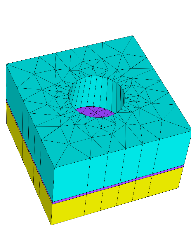
In the previous sections we used periodic boundary conditions for the vertical faces and transparent boundary conditions at bottom and top. With this example we demonstrate how to set boundary identifier for true boundaries of the geometry (neither periodic nor transparent) and how to define holes. Here, the cylinder is now a hole:
This is done by setting the mapped domain identifier to the value 0 which indicates a hole by convention:
Layer {
  ...
  DomainIdMapping = [1 2
                     2 0]
}
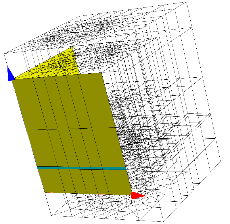
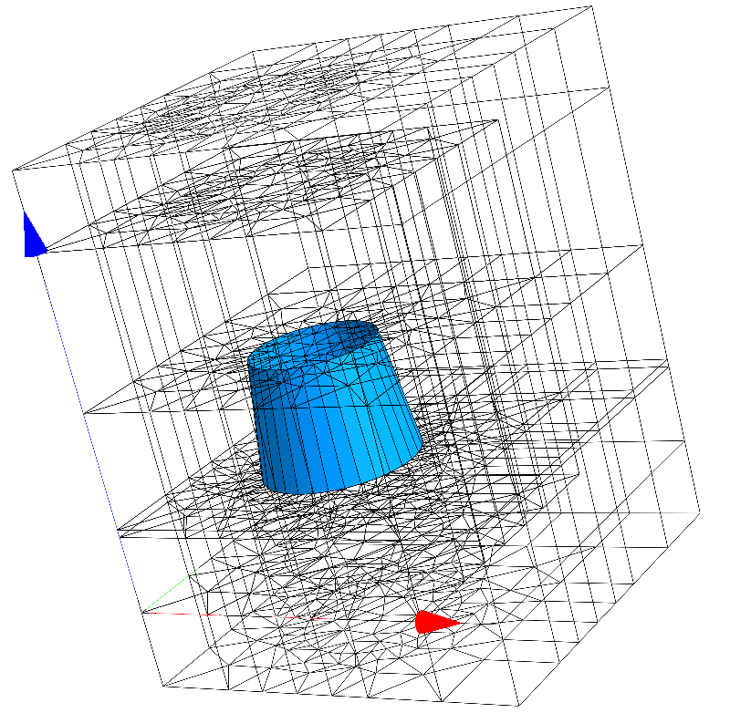
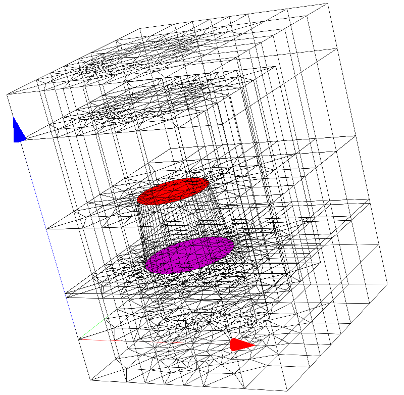
The following figure shows the boundary ids (differently colored) of the computational domain as defined by this example:
 |
 |
 |
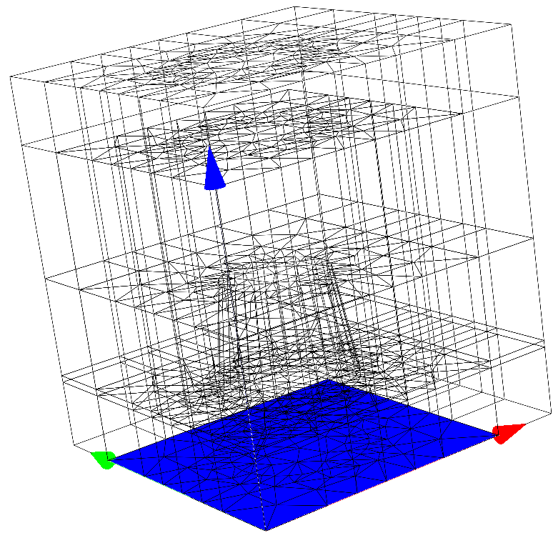 |
Setting the boundary identifier for the 3D geometry follows the same concepts as the domain identifier mapping:
.jcm Input File
layout.jcm [ASCII]
 1
 2
 3
 4
 5
 6
 7
 8
 9
10
11
12
13
14
15
16
17
18
19
20
21
22
23
24
25
26
27
28
29
30
31
32
33
34
35
36
37
38
39
40
41
42
43
44
45
46
47
48
49
50
51
52
53
54
55
56
57
58
59
60
61
62
63
64
65
66
67
68
69
70
71
72
73
74
75
Layout3D {
  Name = "TutorialExample3D"
  UnitOfLength = 1e-06
  MeshOptions {
    MaximumSideLength = 1.3
  }
  BoundaryConditions {
    Boundary {
      Direction = [X, Y]
      Class = Transparent
    }
    Boundary {
      Direction = [-X, -Y]
      BoundaryId = 1
    }
    Boundary {
      Direction = -Z
      BoundaryId = 6
    }
    Boundary {
      Direction = Z
      Class = Transparent
    }
  }
  Extrusion {
    Objects {
      Polygon {
        Name = "ComputationalDomain/Background"
        DomainId = 1
        Priority = -1
        Points = [-2 -2, 2 -2, 2 2, -2 2]
      }

      Circle {
        Name = "Circle"
        DomainId = 2
        Radius = 1
        RefineAll = 2
        Boundary {
          BoundaryId = 5
        }
      }
    }
    MultiLayer {
      Layer {
        Thickness = 1.0
        DomainId = 1
      }
      Layer {
        Thickness = 0.1
        DomainId = 4
        BoundaryIdMapping = [1 2]
      }
      LayerInterface {
        BoundaryId = 3
        GlobalZ = 0.0
      }
      Layer {
        Thickness = 1.5
        DomainIdMapping = [1 2
        2 0]
      }
      LayerInterface {
        GeometryValues = [
        Circle/Radius = 0.8
        ]
        BoundaryId = 4
      }
      Layer {
        Thickness = 2.0
        DomainIdMapping = [1 3]
      }
    }
  }
}
Note
- The boundary id as defined for a segment of the 2D cross section layout is extruded to the corresponding vertical faces. This rule applies for the vertical boundaries of the first layer (left upper figure, yellow area).
- Within a
Layerdefinition aBoundaryIdMapping(similar toDomainIdMapping) maps 2D boundary ids to 3D vertical boundary ids as actual used in the 3D mesh. This rule applies for the second layer (left upper figure, blue area). - Boundary ids for horizontal faces are set within a
LayerInterface. This rule applies for the bottom interface and for the cylinder’s top and bottom faces (left/right lower figures).
