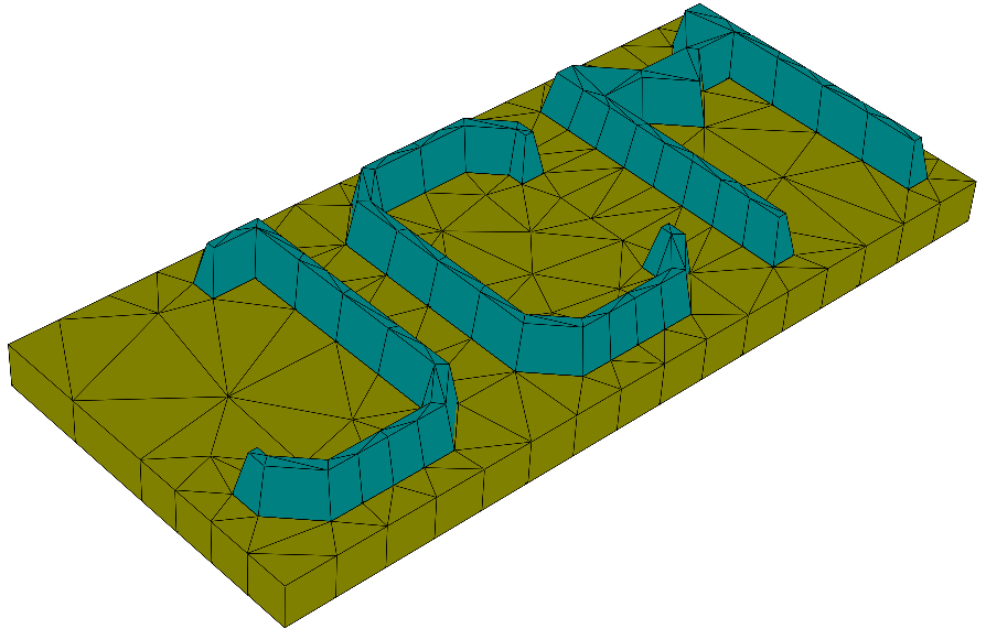
GDSII with Sidewall Angles
Learning targets
- 3D objects with non-rectangular sidewalls in z-direction
- Extrusion of parameterized 2D objects
LayerInterface: Attribute parameter values to extruded 2D objects at the interfaces of 3D layers
This tutorial example contains a 3D layout representing two cones stacked upon each other. The following figure shows the geometry and mesh:

This geometry is constructed by simply defining a circle with variable
radius in the 2D part of the layout, and by attributing different
radii at the interfaces between adjacent layers in the
Extrusion section of the layout.
Attribute specific values to parameters in the Extrusion
In the height profile, LayerInterface sections are defined between
subsequent layers. At the interfaces of these layers, the 2D cross-section parameters
will be attributed specific values. To refer to a cross-section parameter we use the object name followed
by the parameter key tag. E.g., at the interface between the lower and the upper cones of this tutorial example
the radius is defined by
LayerInterface {
  GeometryValues = [Circle_for_extrusion/Radius:1.5]
}
while at the other interfaces, it is given a larger radius. Instead of using the user-defined object name Circle_for_extrusion
one may use the default object identifier Circle(i), where the index i refers to number of circles as defined in the cross-section.
Note
- In the layer between two layer interfaces, the parameter values will be interpolated linearly.
- An arbitrary number of geometry parameters can be defined.
- Parameter variations which lead to changes in topology typically will not be meshed.
.jcm Input File
layout.jcm [ASCII]
 1
 2
 3
 4
 5
 6
 7
 8
 9
10
11
12
13
14
15
16
17
18
19
20
21
22
23
24
25
26
27
28
29
30
31
32
33
34
35
36
37
38
39
40
41
42
43
44
45
46
47
48
49
50
51
52
53
54
55
56
57
58
Layout3D {
  Name = "Layout3D_with_GDSII"
  UnitOfLength = 1e-9
  Extrusion {
    Objects {
      Polygon {
        Name = "GDSPolygon"
        GDS2 {
          Filename = "gds_example.gds"
          Layer = 1
        }
        DomainId = 2
        NormalDisplacement = 20
      }

      Parallelogram {
        DomainId = 1
        Priority = -1
        BoundingBox {
          Offset = [50 50 50 50 ]
          Parent = "GDSPolygon"
        }
        Boundary {
          Class = Periodic
        }
      }
    }
    MultiLayer {

      LayerInterface {
        BoundaryClass = Transparent
      }

      Layer {
        Thickness = 100
        DomainId = 1
      }

      Layer {
        Thickness = 100
        DomainIdMapping = [1 3 2 2]
      }
      LayerInterface {
        GeometryValues = [
        GDSPolygon/NormalDisplacement = 40
        ]
      }
      Layer {
        Thickness = 100
        DomainId = 4
      }
      LayerInterface {
        BoundaryClass = Transparent
      }
    }
  }
}