Isolated Line
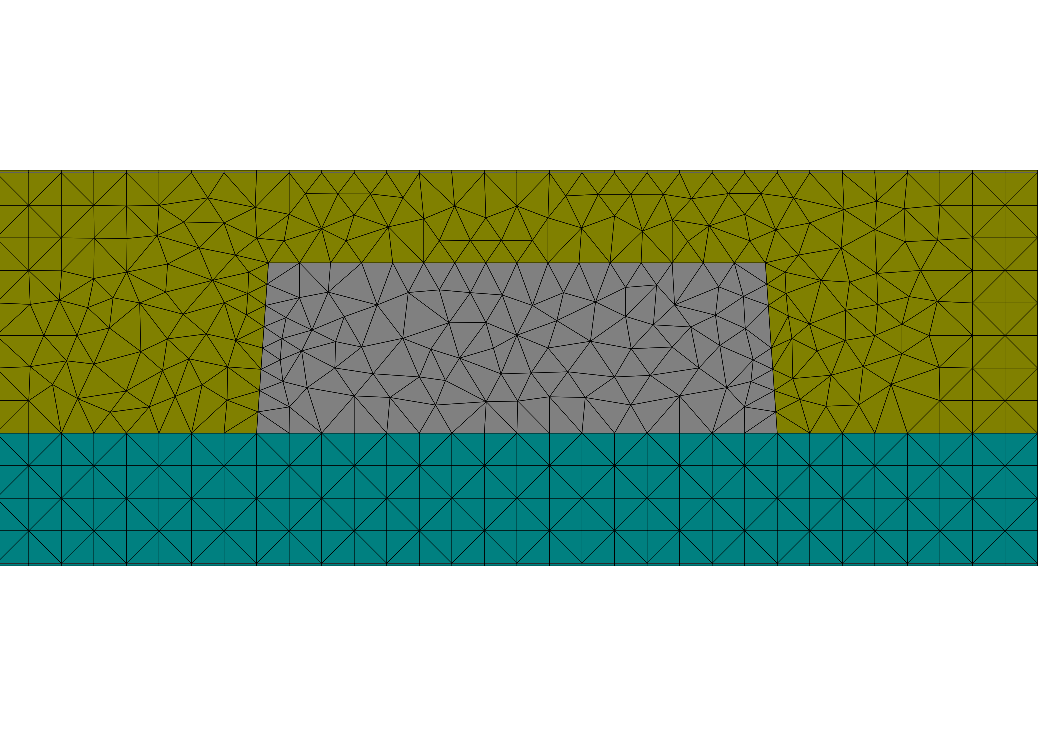
This is a simple example for a 1D isolated line grating. The setup is identically to the periodic line grating example Line Grating but instead periodically arranged lines a single line is now used. Therefore, instead of periodic boundary conditions in horizontal direction the 2D computational domain is equipped with transparent boundaries in both horizontal and vertical directions.
The line is illuminated by plane waves with  and
and  polarization under oblique incidence.
JCMsuite computes the near field distributions.
The following figures show the near-field intensities within the structure for
perpendicular plane wave incidence from the substrate side at a wavelength of  .
.
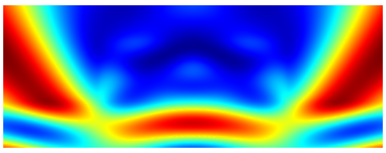
Near field intensity for  -polarized illumination
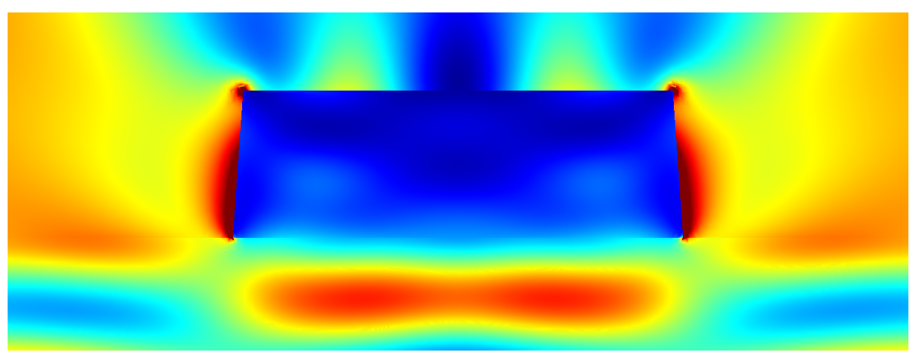
Near field intensity for  -polarized illumination
The post process FourierTransform computes the Fourier transform of the scattered field in the upper half space.
In an experiment the far field is typically collected by an optical setup forming an image. The post-process OpticalImaging allows to describe a general optical imaging system. We demonstrate this for a simple  -magnification tool without aberrations.
PostProcess {
  OpticalImaging {
  InputFileName = "project_results/transmitted_fourier_transform.jcm"
  OutputFileName = "project_results/image_fourier_transform.jcm"
  OpticalSystem {
    SpotMagnification = 2.0
  }
}
The output file fourier_transform_image.jcm" contains the Fourier transform of the field, after passing the optical system.
You can use a Cartesian export post-process to compute the coherent image.
The following figure shows the image in different  -slices (image planes displaced along
  -direction), for
  -polarized illumination.
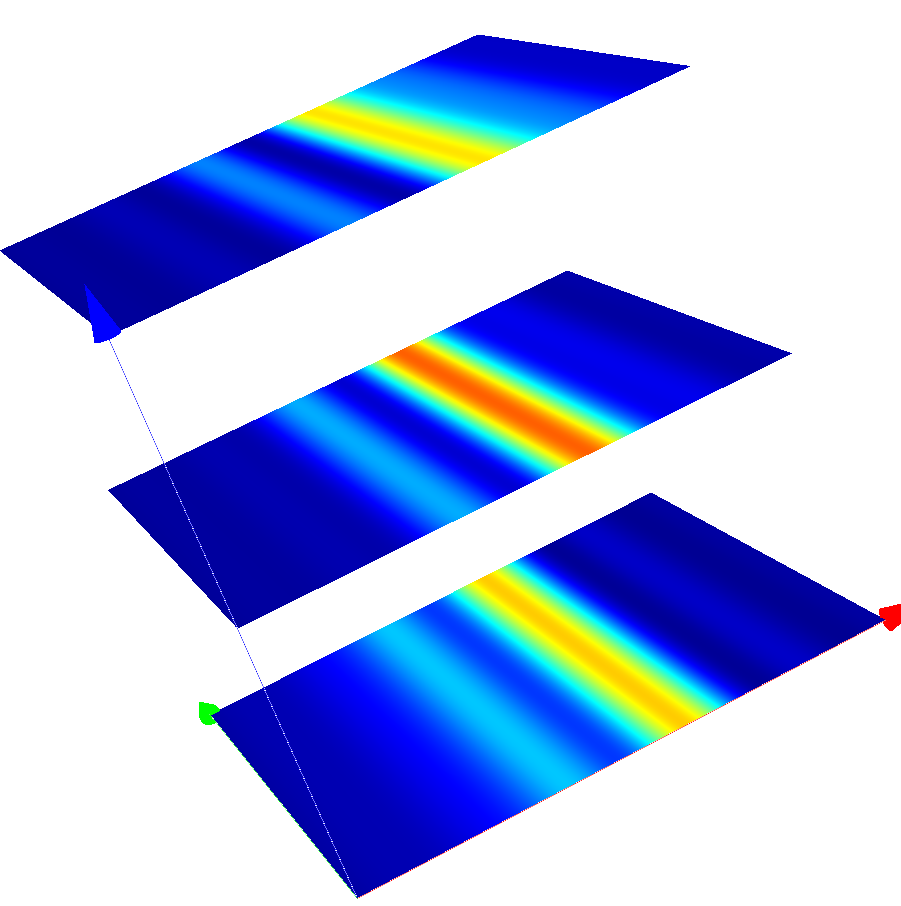
Coherent images of the line after passing the optical system (s-polarized incoming plane wave)
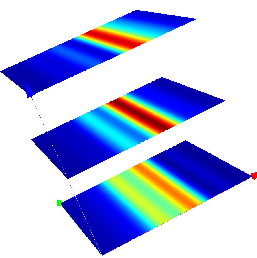
Coherent images of the line after passing the optical system (p-polarized incoming plane wave)
