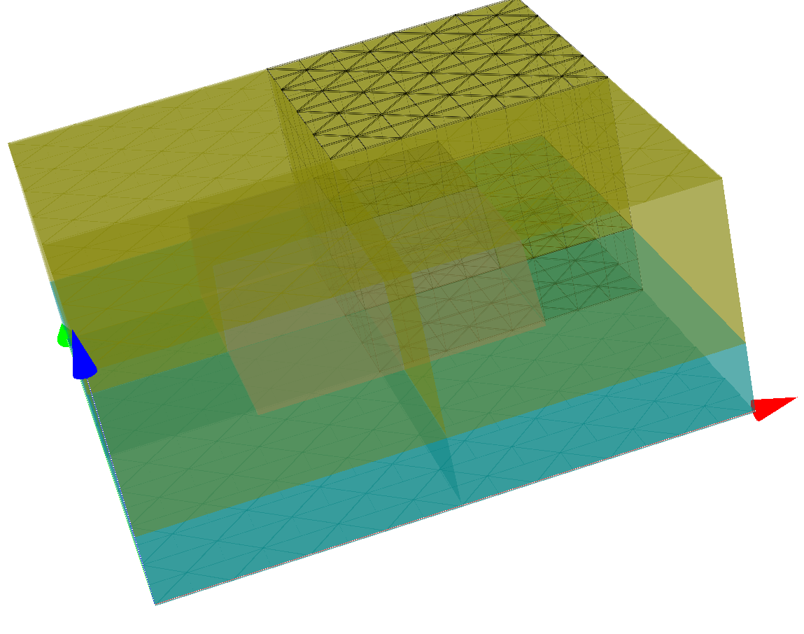
Exploiting Mirror Symmetry
The unit-cell geometry of the parent section exhibits two mirror symmetries (across  - and
- and  planes). This allows to restricts the computational domain to the upper right quarter domain (in the
  plane) for a perpendicular light incidence.

Mesh with mirror symmetries applied. The geometry is discretized only on a quarter domain.
Note
In this periodic setting, for general oblique incidence the mirror symmetry is broken and it is necessary to simulate on the entire domain. This is in contrast to isolated problems (non-periodic) where the presence of mirror symmetries allows a reduction of the computational domain for any source case.
Note
It is also possible to apply only one mirror plane (half computational domain). In this case oblique incidence is compatible with the mirror symmetry as long as the  lies within the mirror plane.
In this example the geometry in layout.jcm is defined as an extrusion of a 2D rectangular domain with a square pattern. To impose mirror boundary conditions the 2D base computational domain is restricted to the upper right square and Class is changed to Mirror for all Boundary segments. (The previously periodified segments also appears as mirror planes now).
Layout3D {
  Extrusion {
    Objects {
      Parallelogram {
        DomainId = 1
        Priority = ComputationalDomain
        ...
        Boundary {
          Class = Mirror
        }
      }

      Parallelogram {
        Name = "Pattern"
        DomainId = 2
        ...
      }
      ...
    }
    MultiLayer {
      ...
    }
  }
}